Solar SPD and Surge Arrester in Utility-Scale Solar Plants: Three Protection Zones Documented from the Field
A surge event in a utility-scale solar plant does not appear in SCADA the moment it occurs.The alarm often appears seconds later as an inverter fault code, an unexpected trip, or a PV string showing no generation. By then, the metal oxide varistor (MOV) inside the solar SPD has either absorbed the overvoltage transient or failed to do so, and the resulting surge may have damaged the inverter input capacitors, an IGBT gate driver, or a string combiner fuse. Generation is lost, and the root-cause investigation must start with an event log that recorded the result rather than the cause.
Surge protection in a utility-scale PV plant is not one device near the inverter. It covers three different voltage levels: the high-voltage evacuation substation, the low-voltage AC panel at the inverter output, and the DC side at the string combiner box and inverter input. Each zone addresses a different surge entry path, follows a different IEC standard, and has different parameters to verify during commissioning and O&M inspections.
This article documents surge protection equipment across all three zones from real utility-scale plant installations. Where nameplate data is readable in field photographs, it is quoted directly from what is visible. IEC standard references are cited where applicable. Observations about equipment failures and what is commonly missed during O&M are based on field work, not manufacturer datasheets.
1. Surge Arrester vs. Solar SPD: Not the Same Device
A surge arrester, sometimes called a lightning arrester (LA) on site, is a high-voltage device installed on the MV or HV busbar of a plant's evacuation substation, typically at 11 kV, 33 kV, or 66 kV. It is covered by IEC 60099-4, which specifies requirements for metal-oxide surge arresters without gaps for AC systems, and is selected based on parameters such as MCOV (Maximum Continuous Operating Voltage), rated voltage, and nominal discharge current class.
A surge protection device (SPD) is a low-voltage device installed in string combiner boxes, at inverter DC input terminals, or in AC distribution boards. DC-side SPDs for photovoltaic systems, commonly called solar SPDs, fall under IEC 61643-31. AC-side SPDs fall under IEC 61643-11. Both types are MOV-based, but they operate at fundamentally different voltage levels and energy classes, and they are not interchangeable in either direction.
The reason matters practically. DC fault current has no natural zero crossing. If you wire an AC-rated SPD into a DC string circuit, the MOV absorbs the transient but cannot interrupt the follow current from the DC source. You get a sustained arc or a short-circuit path from the string conductor to earth. That can burn through the SPD housing and trigger a ground fault at the combiner box.
2. Three Protection Zones in a Utility-Scale Solar Plant
Each zone handles the surge energy and entry path appropriate to its voltage level. Residual transients passing through one zone are attenuated before they reach the next. The three zones in a grid-connected utility-scale solar plant are:
- Zone 1 — HV Evacuation Substation: Lightning-induced surges arriving on the grid transmission line or from nearby strikes on the HV yard structures. Surge arresters connect phase-to-earth at the 33 kV or 66 kV busbar, ahead of the step-up power transformer.
- Zone 2 — LV AC Side: Residual transients transferred through the transformer or induced on LV cables between the inverter and the LV busbar. Type 2 AC SPDs installed in the inverter's AC output panel or AC distribution board (ACDB).
- Zone 3 — DC Side: Lightning-induced transients on the DC string cables from the PV array to the combiner box or inverter. DC solar SPDs installed in the string combiner boxes and, in some designs, at the inverter DC input terminals as well.
All three zones must be operational at the same time. A failed Zone 3 SPD leaves the inverter DC input exposed regardless of what is installed at Zones 1 and 2. Each zone handles its own voltage level. SPD coordination across zones is a design task. At O&M, your job is confirming every device across all three zones is operational at each inspection cycle.
3. Zone 1 — HV Surge Arrester at the Evacuation Substation
The HV surge arrester is the first protection layer. Three arresters connect phase-to-earth at the 33 kV or 66 kV busbar, one per phase. Their job is to divert lightning-induced surge currents to the earthing system before they reach the step-up transformer and, through it, the inverter side of the plant.
3.1 Porcelain Body: Older Generation
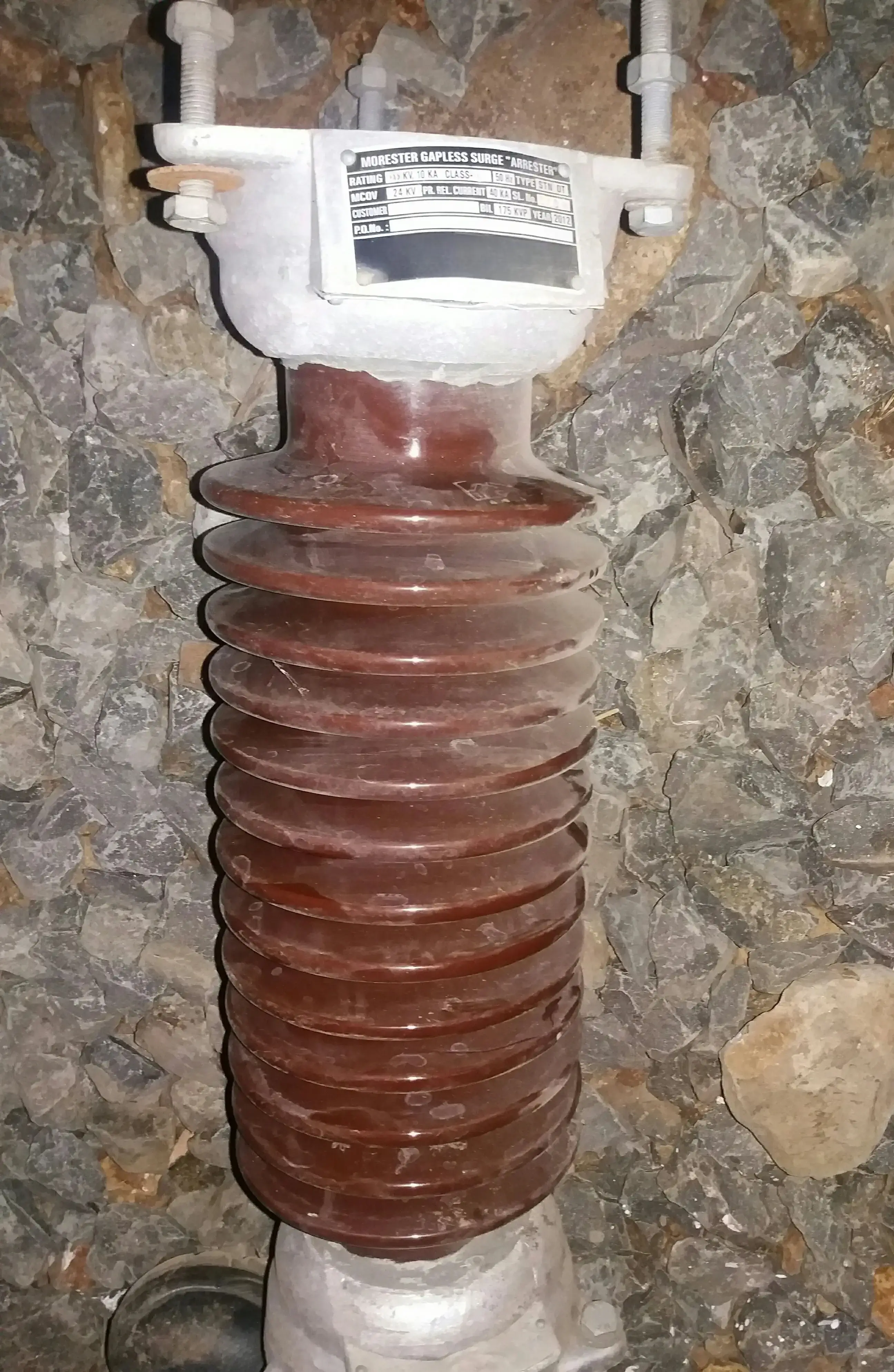
The arrester in this photograph is a 33 kV class gapless surge arrester. Its body is porcelain with eleven disc sheds that provide the creepage distance for the rated voltage. The metal top and bottom caps compress the internal MOV column and form the terminal and earth connection points.
Porcelain-bodied surge arresters were the standard in HV substations for decades. Their electrical performance is not inferior to polymer units. The concern is the failure mode. A porcelain arrester that fails internally from thermal stress can fracture violently, sending ceramic fragments outward. Polymer units fail through housing rupture or pressure relief, which does not produce projectile debris. That difference, combined with the greater shipping weight and fragility of porcelain, drove the shift to polymer housings in newer substations.
3.2 Polymer Body: Current Standard
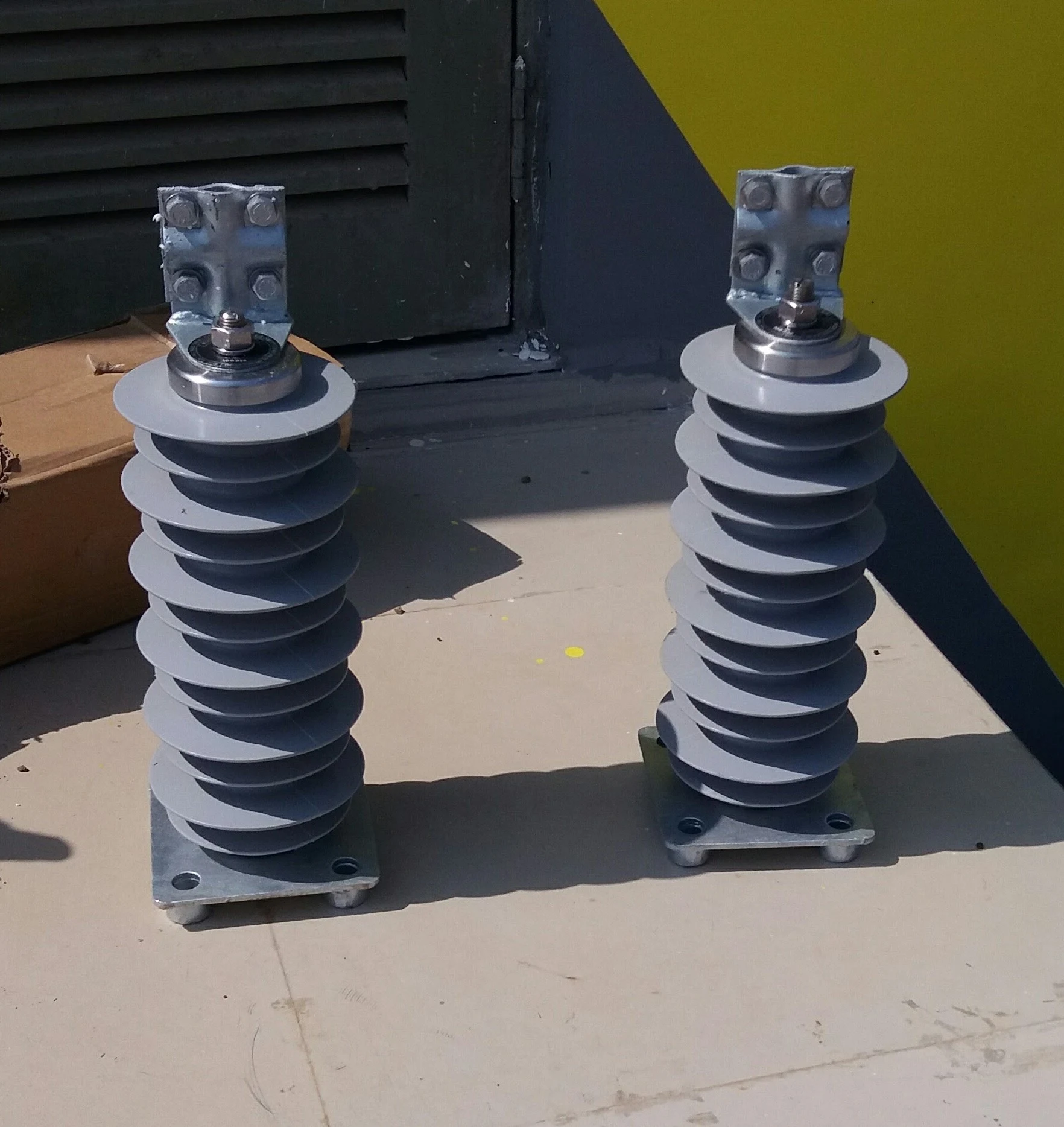
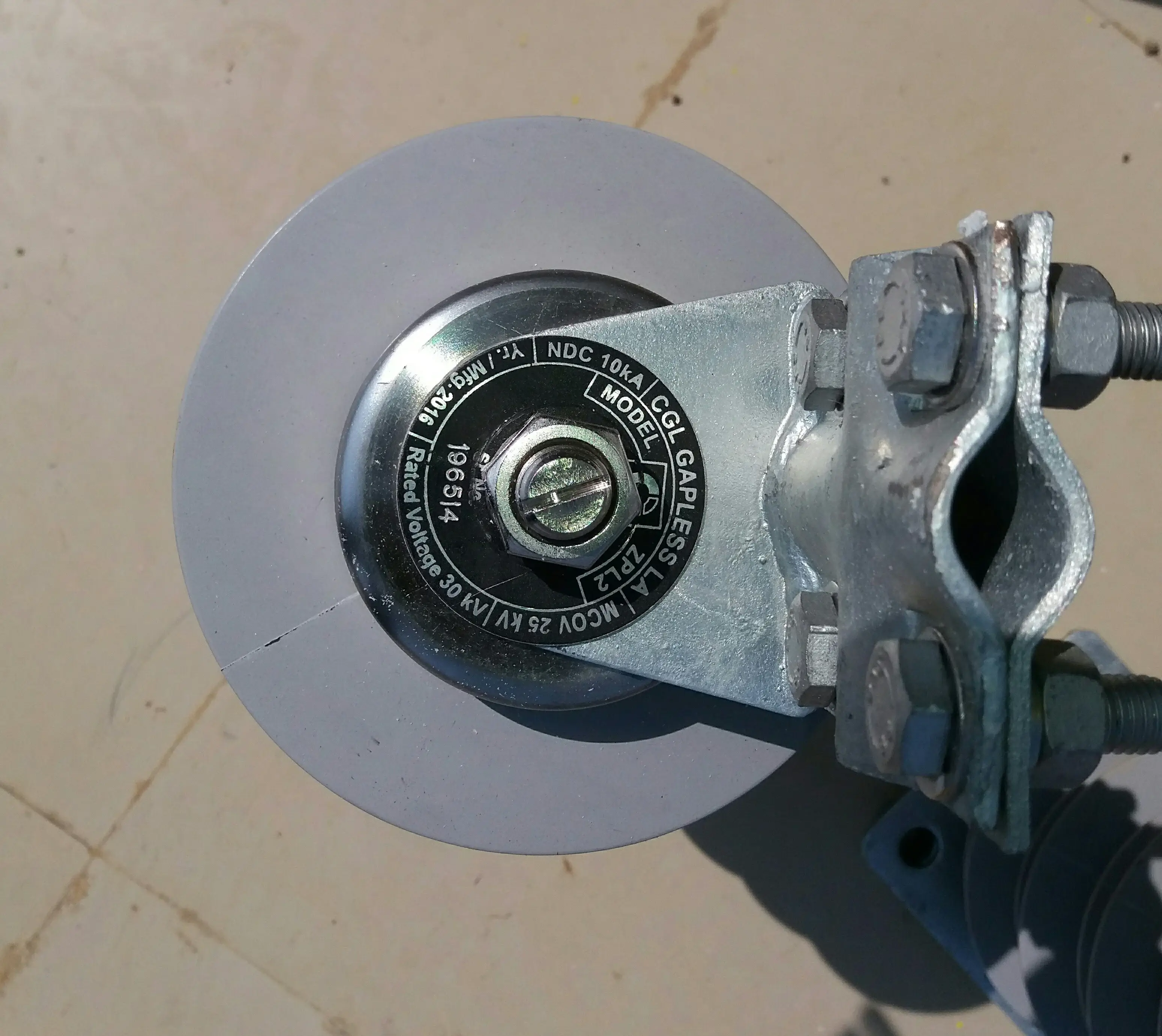
The replacement units in these photographs are gapless polymer lightning arresters, model ZPL2. The bottom cap nameplate is fully readable:
- NDC (Nominal Discharge Current): 10 kA
- MCOV (Maximum Continuous Operating Voltage): 25 kV
- Rated Voltage: 30 kV
An MCOV of 25 kV with a rated voltage of 30 kV fits a 33 kV system using resistance grounding or high-impedance grounding. In that configuration, a phase-to-earth fault pushes the healthy phases toward the full line-to-line voltage for the fault duration. The arrester MCOV must stay above that temporary overvoltage without conducting, which sets the MCOV requirement at 25 kV or higher.
In a solidly earthed 33 kV system, the earth fault factor is typically 1.0 to 1.1. The maximum sustained phase-to-earth voltage during a fault is around 19 to 21 kV. A 21 to 22 kV MCOV arrester fits that grounding arrangement. You cannot select the correct MCOV from line voltage alone. Confirm the neutral grounding arrangement from the substation design documentation before ordering any replacement arrester.
The polymer housing on the ZPL2 units uses silicone rubber sheds over a fiberglass reinforced polymer (FRP) core containing the MOV column. Silicone rubber is hydrophobic. Water does not form a continuous conductive film across the surface, which helps control leakage current in polluted or humid environments. The helical fin profile provides a longer creepage distance in a compact design compared with the stacked shed profile of the porcelain arrester in the same substation.
3.3 Installation and the Ground Connection
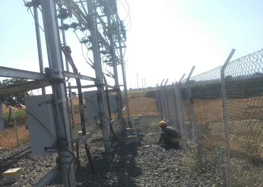
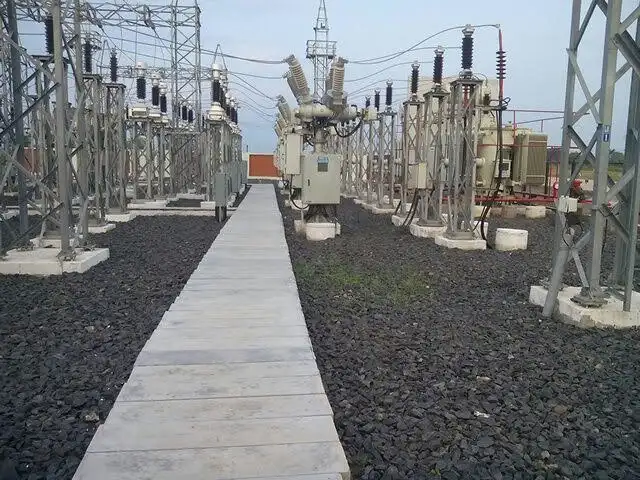
The white square enclosures at ground level are surge counter housings or earthing conductor junction boxes. They provide access to the conductor running from the surge arrester bottom, down the structure leg, and to the station earthing mat. Where a surge counter is installed, you access it through this enclosure. During the annual O&M inspection, record the counter reading and compare it with the previous reading. An increase in the count indicates that the surge arrester has experienced a discharge event since the previous inspection.
The routing of the earthing conductor from the arrester base cap to this junction box directly affects protection performance. Surge discharge current flows through it during every lightning event. Each bend and extra meter adds inductance. At the 1.2 microsecond rise time of a standard lightning impulse, that inductance produces a voltage drop that adds to the voltage reaching the protected equipment above the arrester's rated protection level. Keep the ground conductor short and straight. At site, a common issue is an earthing conductor with multiple bends and excess length, which can be difficult to correct after commissioning.
The arrester's effectiveness also depends on the station earthing system: earth resistance, mat coverage, and bonding integrity. For earthing design and what poor earthing costs in protection performance, see the article on Earthing in Solar Plants and Its Impact on Performance.
4. Zone 2 — AC-Side SPD at the Inverter Output
The AC-side SPD sits between the inverter's AC output terminals and the LV bus or transformer LV winding. It catches residual transients passing through the step-up transformer and transients induced on LV cables inside the plant. These can damage inverter output contactors, protection relays, grid interface monitoring circuits, and AC output filter components.
4.1 Equipment Parameters
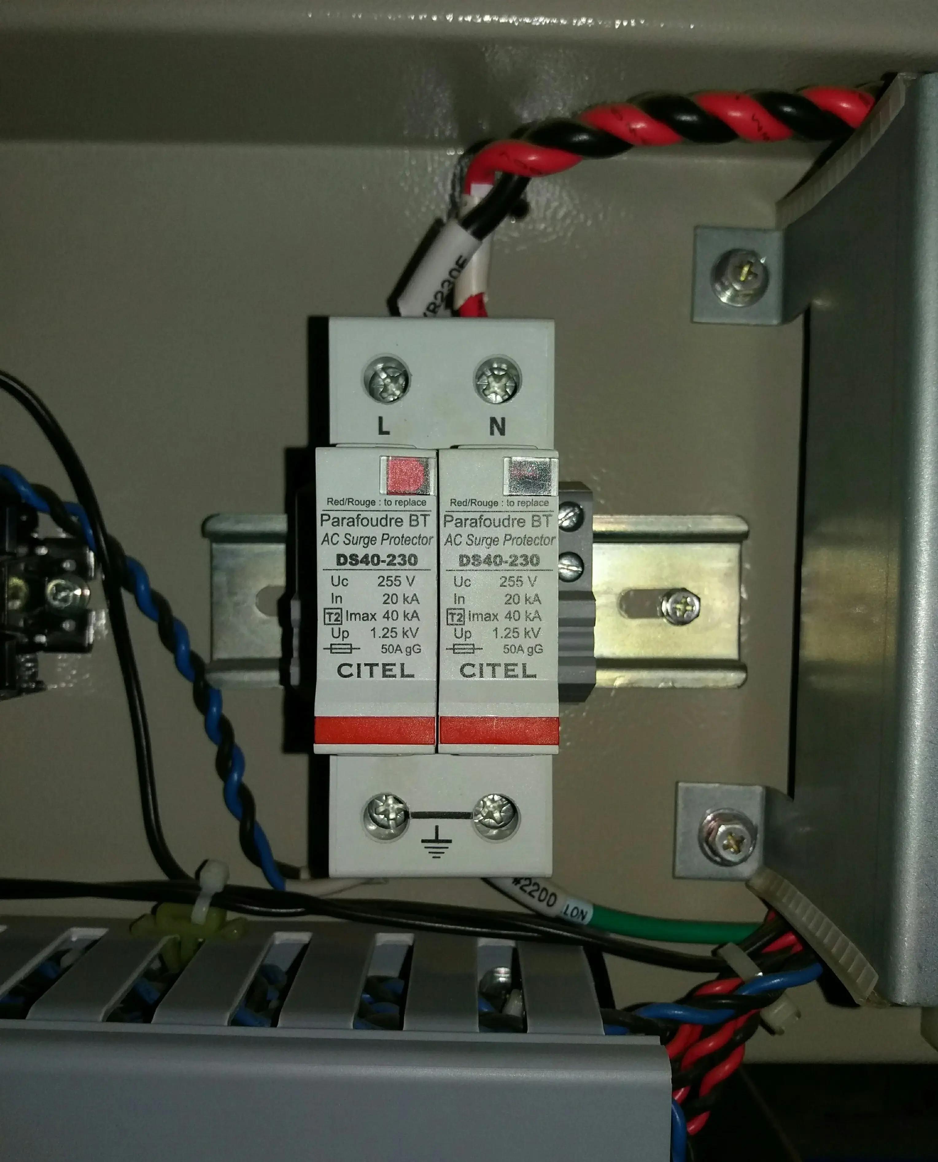
The device in this photograph is an AC Surge Protector, model DS40-230. The nameplate on the module face is fully readable:
- Uc (Maximum Continuous Operating Voltage): 255 V
- In (Nominal Discharge Current): 20 kA
- T2 Imax: 40 kA
- Up (Voltage Protection Level): 1.25 kV
- Backup fuse: 50 A gG
T2 means Type 2 per IEC 61643-11. Type 2 SPDs are tested with an 8/20 microsecond current waveform and handle induced lightning transients and switching events. Type 1 SPDs use the higher-energy 10/350 microsecond waveform and go where direct lightning current may enter the installation. For most utility-scale inverter AC panels, Type 2 is the standard. Where there is a risk of direct lightning current entering the installation, a Type 1+2 combined SPD is used instead of a standalone Type 2 device.
A Uc of 255 V is above 1.1 × Un for a 230 V system (1.1 × 230 = 253 V). This gives a 2 V margin above that value. The 50 A gG backup fuse is a series fuse that disconnects the SPD from the AC supply if the MOV fails short-circuit. Without it, a shorted MOV creates a permanent fault on the protected circuit.
4.2 The Status Indicator: What This Photograph Shows
The left module shows a red status indicator. The label reads "Red/Rouge: to replace." This is not a manufacturing defect. This is a real condition found during an inspection.
A red status means the internal thermal disconnector has tripped. The MOV is isolated from the circuit. That module no longer protects the Line conductor. The inverter keeps running at full output. SCADA shows no alarm. Your generation figures look normal for the day. The only way you find this is by physically looking at the device.
The right module, protecting the Neutral conductor, still shows operational status. That split condition is common. A surge that operated the L-phase MOV was not energetic enough to operate the N-phase MOV, depending on how the transient entered the circuit. Check both modules separately at every inspection. Confirming one is operational and assuming the other is fine will miss a split failure.
The status indicator on these modules face the panel interior and are visible from the door opening without accessing any energized compartments. If the installer had oriented the modules against the back wall or behind cable trunking, you would need additional access steps to inspect them. Check status indicator orientation during factory acceptance testing (FAT) of any pre-wired panel or combiner box before it leaves the manufacturer.
5. Zone 3 — DC-Side Solar SPD at the String Combiner and Inverter Input
The DC solar SPD is the protection layer closest to the array. In a 10 MW block with 20 string combiner boxes, you have 20 separate SPD assemblies. In a three-pole setup, that is 60 status windows to check independently. This zone is where failed devices most often go undetected after commissioning. There is no warning on SCADA when a DC solar SPD fails, and the inspection workload at the combiner box level is high.
String cables run unshielded over open ground from the module rows to the combiner box. Runs of 200 to 400 m are common in utility-scale plants. A nearby lightning strike, even one that does not directly contact any part of the PV system, can induce a voltage transient on a 300 m string cable run that is sufficient to exceed the withstand voltage of input filter capacitors or gate driver circuits in an inverter. The solar SPD at the combiner box is where that transient can be clamped before it reaches the inverter.
5.1 Equipment Parameters
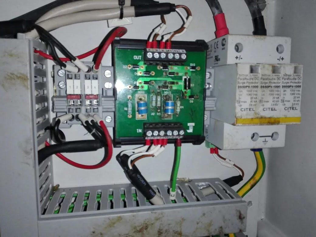
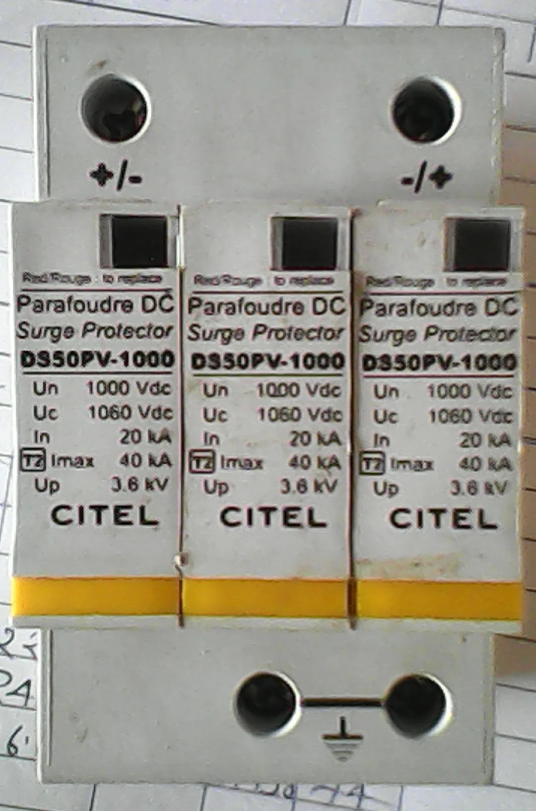
The DC solar SPD in these photographs is model DS50PV-1000. Three modules form one assembly. From the nameplate:
- Un (Nominal Voltage): 1000 Vdc
- Uc (Maximum Continuous Operating Voltage): 1060 Vdc
- In (Nominal Discharge Current): 20 kA
- T2 Imax: 40 kA
- Up (Voltage Protection Level): 3.6 kV
The three-module setup protects the positive string conductor, the negative string conductor, and provides discharge paths relative to protective earth (PE). The terminal markings in the close-up, "+/-" on one module and "-/+" on another, confirm each module clamps one conductor to PE when its voltage rises above the operating threshold. In a standard floating PV array, both positive and negative conductors carry significant voltage relative to earth, so both need protection.
T2 Imax of 40 kA confirms this device follows the 8/20 microsecond Type 2 waveform per IEC 61643-31. At the combiner box position, 20 kA nominal and 40 kA maximum is the standard energy class. If the combiner box is in an area where the PV array could be directly struck by lightning (for example, an open field plant at a high-altitude site), a Type 1+2 DC SPD with a higher energy class and a 10/350 μs withstand rating is specified at the first combiner box in each zone.
5.2 Why Uc Is the Critical Parameter
Uc must stay above the highest voltage that appears at the SPD terminals during normal operation. For a DC PV string, that peak is the open-circuit voltage under minimum temperature conditions, not the STC Voc and not the nominal system voltage.
Crystalline silicon modules produce higher Voc at lower cell temperatures. The Voc temperature coefficient (typically negative 0.28 to negative 0.34 percent per degree Celsius) means every degree below 25 degrees Celsius adds string voltage. A string designed to stay within 1000 Vdc at STC can reach 1045 to 1060 Vdc when cell temperature drops to 5 degrees Celsius, depending on the module coefficient and number of series modules.
The Uc on the SPD shown here is 1060 Vdc. That leaves a small margin above the upper end of that cold-morning range. If you select a DC solar SPD with Uc below your string's actual maximum cold-day Voc, the MOV starts conducting during normal operation, not during a surge event. It heats progressively. Eventually the thermal disconnector trips, the status indicator turns red, and you have a device that degraded from sustained conduction rather than from doing its job. In some cases the internal disconnector does not clear, the SPD develops a short-circuit path to earth, and you have a ground fault at the combiner box.
For how DC-side ground faults affect inverter performance before a trip occurs, see the article on Ground Faults Reduce Solar Plant Performance Before Inverter Trips.
IEC 61643-31 gives you the Uc calculation method. It uses the Voc temperature coefficient from the module datasheet, the number of series modules, the site's minimum temperature, and a safety factor. Use the actual module data and your site's temperature record. The nominal system class voltage is a starting point, not the calculation.
6. Parameters to Evaluate Before Accepting an SPD
The parameters on SPD and surge arrester nameplates follow consistent definitions once the underlying concepts are clear. The table below uses the data readable directly from field photographs across all three protection zones in this article.
| Parameter | HV Surge Arrester (model ZPL2 — Zone 1) | AC SPD (model DS40-230 — Zone 2) | DC Solar SPD (model DS50PV-1000 — Zone 3) |
|---|---|---|---|
| Voltage rating | 30 kV (rated voltage, Ur) | — | 1000 Vdc (Un) |
| MCOV / Uc | 25 kV (MCOV) | 255 V (Uc) | 1060 Vdc (Uc) |
| Nominal Discharge Current (In) | 10 kA (NDC) | 20 kA | 20 kA |
| Maximum Discharge Current (Imax) | — | 40 kA (Type 2) | 40 kA (Type 2) |
| Voltage Protection Level (Up) | — | 1.25 kV | 3.6 kV |
| Governing Standard | IEC 60099-4 | IEC 61643-11 | IEC 61643-31 |
| Housing material | Polymer (silicone/FRP) | Thermoplastic (DIN rail) | Thermoplastic (DIN rail) |
| Test waveform (In/Imax) | 8/20 μs (NDC class) | 8/20 μs (Type 2) | 8/20 μs (Type 2) |
Up is the peak voltage the SPD terminals see during the standard test discharge. Equipment on the protected side must have an impulse withstand voltage above Up. For the AC SPD, Up is 1.25 kV. Inverter AC output components are typically rated at 2.5 kV impulse or higher, so the margin is adequate. For the DC solar SPD, Up is 3.6 kV. Utility-scale central inverter DC input stages are generally rated at 4 kV impulse or higher. Confirm this against your specific inverter's technical specification during design. Do not assume it from the model family.
A lower Up gives better protection because it limits the peak voltage that reaches the equipment below a lower threshold. Lower Up typically comes with a higher Uc requirement and more demanding MOV materials. The selection balances protection level, energy handling capacity, and Uc margin for the installation.
7. SPD Failure and Its Impact on Plant Availability and CUF
A failed SPD produces no SCADA alarm. The inverter continues generating at full capacity. Monthly PR and CUF figures look normal. The only visible sign is the status indicator on the physical device during a site visit. This is what separates surge protection failure from almost every other O&M problem: the failed device is invisible to remote monitoring until the next surge proves it.
What you lose is not immediate generation. What you lose is protection. When the next surge reaches the unprotected terminal, there is no discharge path to earth. The transient rises to whatever level the source drives it. For a central or string inverter DC input, that typically means capacitor insulation breakdown, gate driver circuit flashover, IGBT damage, and a fault trip. The inverter goes offline. Fault investigation and repair take hours to days depending on spare parts availability.
For the relationship between IGBT electrical stress damage and the resulting performance degradation in a utility-scale central inverter, see the article on IGBT Failure in Utility-Scale Solar Inverters.
To estimate the generation lost during an unplanned inverter trip (from any cause, including a surge-induced fault), the Plant & Grid Generation Loss calculator estimates lost energy in kWh from the plane-of-array irradiance recorded during the downtime period. When a surge-related trip occurs during a high-irradiance period, the energy loss per hour can be higher than the plant's average loss per downtime hour.
For formal O&M contract reporting, the impact of an inverter trip on availability depends on the availability methodology used in the contract or reporting standard. The Plant & Grid Availability tool uses an irradiance-weighted approach, so periods with higher irradiance have a greater effect on the calculated availability than periods with lower irradiance. For example, a one-hour trip at noon during 800 W/m² irradiance would have a greater impact under this method than a one-hour trip at 06:00 AM during 100 W/m² irradiance. Therefore, a surge-related inverter trip during high irradiance can have a larger impact on availability, even with short downtime.
Replacing a failed SPD cartridge costs a fraction of an inverter repair. The main challenge is detection, not cost. Checking the SPD status indicator on every combiner box during site inspections is a simple way to find failed SPDs before the next surge event occurs.
7.1 Solar Panel Fire from DC SPD Failure: A 250 kWp Rooftop Case
I was called to investigate a fire incident at a 250 kWp rooftop solar plant. The site team had already isolated the affected section by the time I arrived. Eight modules were destroyed. The corrugated metal roof beneath them had taken sustained heat from above. The rest of the plant was running.
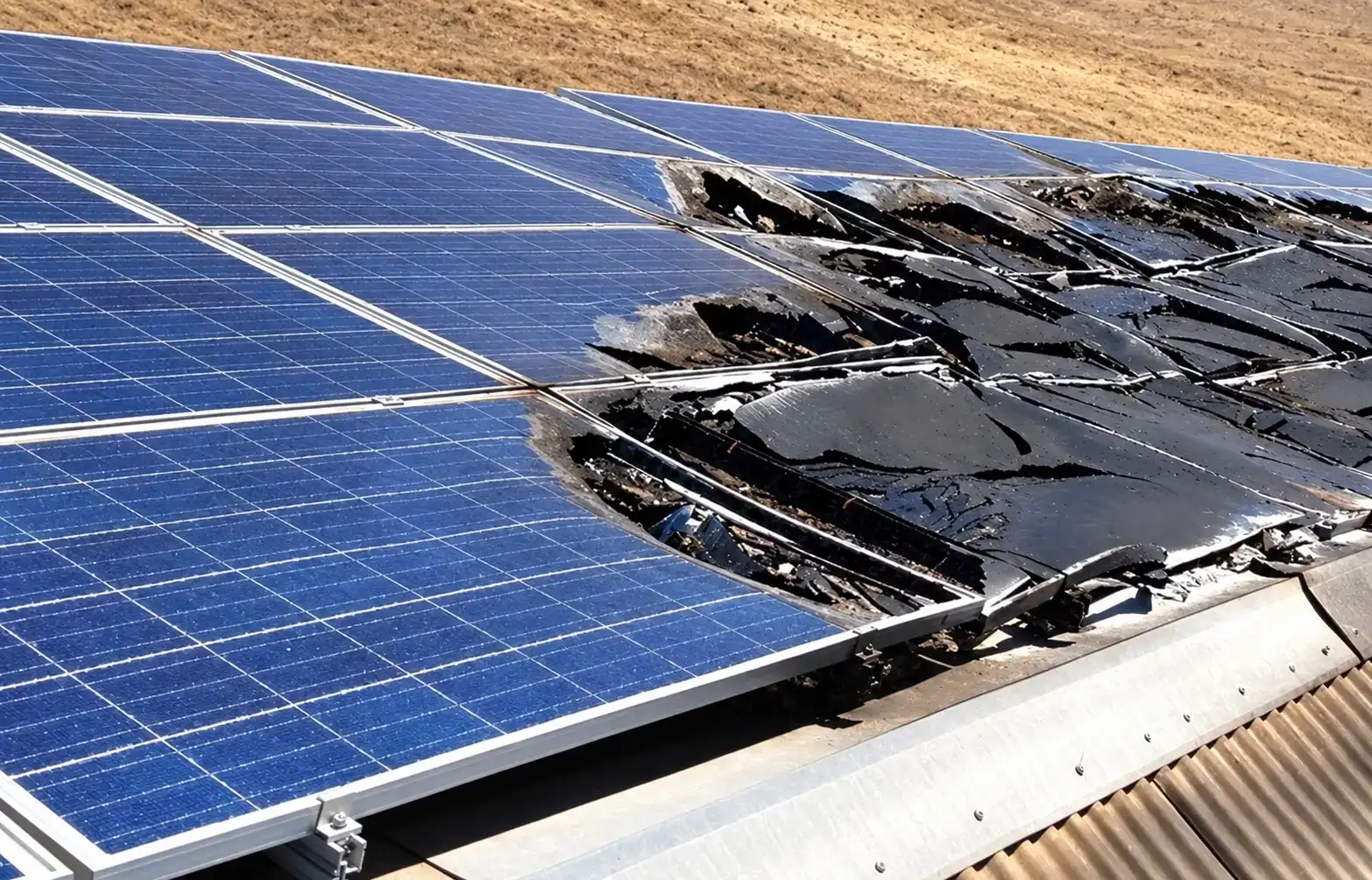
Before touching anything, I read the burn pattern from above. The damage was limited to a contiguous block of eight modules, with the backsheet burned through and melted black polymer collected around the damaged areas. Frames were also deformed from sustained heat. The two modules immediately outside the damaged section showed no thermal damage. This pattern points away from an external fire source and indicates that the fault originated within the string and progressed from module to module.
I went to the string combiner box. The DC solar SPD module for the affected string had its status indicator showing red. The internal thermal disconnector had tripped. The device had absorbed a surge event at some point prior to the fire and was no longer functioning. Nobody had checked it. There was no O&M record of the last combiner box inspection that included SPD status verification. The plant had been running unprotected on that string since the SPD failed.
The sequence from there is not difficult to reconstruct. A transient arrived on the string cable, most likely lightning-induced. With no functioning SPD on that string, there was no discharge path to earth. The transient energy reached the conductors directly and broke down the insulation at one point on the string. A DC arc established there.
DC arcs do not self-extinguish. AC current crosses zero 100 times per second at 50 Hz, and the arc breaks at that zero crossing if the restrike voltage is insufficient. DC current from a live PV string has no zero crossing. The array on a clear day holds its open-circuit voltage regardless of a fault anywhere on the string. Once the arc established at the insulation failure point, the string kept feeding it. The heat built progressively. The backsheet ignited. The encapsulant burned. The flame front moved to the next adjacent module as heat transferred through the shared frame contact. Eight modules in sequence. Then it stopped, because the string was now open-circuit and the arc lost its supply.
Eight modules at around 430 Wp each amounts to 3.44 kWp on a 250 kWp plant, which is just over 1% of installed capacity. The replacement and labor costs are a fixed number. What takes longer to assess is the corrugated metal roof structure beneath the burned section, which absorbed sustained radiant and conductive heat from above. That structure needs inspection before new modules go back on. The generation loss during the isolation and repair period is calculable using irradiance data from the downtime window. The Plant & Grid Generation Loss calculator estimates exactly that figure from the irradiance recorded while the plant was offline.
8. Field Observations and Common Mistakes
Status indicators facing the wrong direction
SPD modules installed with the status indicator against the back wall or blocked by cable trunking. You cannot check the indicator without removing cables. The problem can be avoided by checking during the factory acceptance test (FAT) that the status indicator of every SPD is clearly visible from the front of the combiner box.
Uc selected from system voltage, not from Voc temperature calculation
DC solar SPDs selected with Uc equal to the system class voltage, 1000 Vdc, without calculating the maximum string Voc at the site's lowest cell temperature. The MOV conducts during cold high-irradiance mornings. It degrades. The status indicator eventually turns red. The cause is not a surge event. It is a wrong selection that stressed the MOV from day one of operation.
Missing or undersized ground conductor at the combiner box
The SPD PE terminal is connected to the combiner box chassis, but the chassis is not properly connected to the plant earthing system. During a surge, current that should flow to earth instead circulates through chassis metalwork and returns through monitoring cables or signal wiring. That puts a transient onto the data network at the exact moment the SCADA hardware is most exposed to it.
Surge arrester replaced without confirming grounding arrangement
A failed surge arrester should not be replaced based on 33 kV line voltage alone. The required MCOV depends on the neutral grounding arrangement and expected temporary overvoltages. An arrester with insufficient MCOV experiences excessive stress and ages prematurely. The replacement should therefore match the site's grounding conditions and the manufacturer's requirements.
Arrester ground conductor with excessive bends
Ground conductors routed with multiple 90-degree bends to avoid obstructions. Each bend adds inductance to the discharge path. At the 1.2 microsecond rise time of a lightning impulse, that inductance adds to the voltage reaching the protected equipment above the arrester's rated Up. The correct approach: shortest path, fewest bends, adequate conductor cross-section.
9. O&M Inspection Checks
DC Solar SPD — Monthly or Quarterly
- Inspect every DC SPD module in each string combiner box. Check the modules individually because one can fail while the others remain operational. A red indicator means the module needs replacement.
- Make sure the conductor from the SPD PE terminal to the combiner box earth bar is tight and free from physical damage or corrosion.
- Confirm that the combiner box earth bar is connected to the plant earthing system. A poor connection can reduce the SPD's ability to safely discharge surge current.
- Record the status of each SPD in the O&M logbook and compare it with the previous inspection. If a module has changed to red, review the inverter event log and site weather records for any related surge or fault event.
AC-Side SPD — Monthly or at Every Inverter Inspection Visit
- Check the L-phase and N-phase module indicators separately. One can fail while the other stays operational.
- Verify the 50 A gG backup fuse is intact. During a de-energized maintenance period, check continuity with a multimeter.
- Make sure the SPD is securely seated on the DIN rail, as vibration from the inverter transformer and fans can loosen DIN rail-mounted devices over time, and ensure that the SPD terminals are not under mechanical stress from the cables.
HV Surge Arrester — Annual or After a Confirmed Lightning Event
- Inspect polymer housings for tracking marks, carbonization, or physical cracks. Any signs of tracking or surface discharge should be investigated.
- Record the discharge counter reading at each arrester base enclosure and compare with the previous inspection. A large increment indicates multiple discharge events and warrants a closer inspection.
- Check the ground conductor clamp at the base cap and the connection at the earthing junction box. Both must be mechanically tight. A loose connection raises the ground path impedance and reduces the arrester's protection level.
- Thermography during operation can identify abnormal heating in degraded MOV blocks before the degradation becomes a failure. For porcelain-bodied arresters whose internal condition is not visible externally, thermography is the most practical condition assessment tool available without de-energizing.
For how string-level monitoring can help detect PV module insulation or bypass diode damage after a lightning event, see the article on String-Level Monitoring vs Plant-Level Monitoring. Partial damage may not stop a string completely, but its reduced output can show up as a drop from its normal performance level in string-level current or power data.
10. What to Confirm at Every Zone
- HV surge arresters and solar SPDs are not interchangeable. IEC 60099-4 covers HV arresters. IEC 61643-31 covers PV DC SPDs. IEC 61643-11 covers AC SPDs. Using the wrong device at the wrong voltage level can fail in a way that creates a hazard rather than providing protection.
- All three protection zones must be operational at the same time. A failed DC solar SPD at Zone 3 leaves the inverter DC input exposed regardless of what is installed at Zones 1 and 2.
- HV arrester MCOV depends on the substation neutral grounding arrangement, not the line voltage. Confirm the grounding type from the substation design documentation before ordering a replacement.
- A red SPD status indicator means the module has reached its replacement condition. The failed module does not produce a SCADA alarm. Physical inspection is your only detection mechanism. Inspect each pole separately.
- DC solar SPD Uc selection requires calculating the maximum string Voc at the site's minimum temperature using the module's Voc temperature coefficient and number of series modules. The nominal system class voltage is not the calculation.
- The earthing connection is a critical part of surge protection. Poor connections and excessive impedance reduce the SPD's or arrester's ability to divert surge current safely.
- A failed SPD does not cause immediate generation loss. The bigger risk is that the next surge can damage equipment, cause an inverter trip, and lead to lost energy and availability.
- If a failed DC SPD develops a short circuit and its protective device does not disconnect it, a ground fault can occur at the combiner box.
Frequently Asked Questions
What is a solar SPD and where is it installed in a utility-scale solar plant?
A solar SPD protects PV equipment from transient overvoltages caused by nearby lightning strikes and switching events. DC solar SPDs go in string combiner boxes and at the inverter DC input terminals. PV DC SPDs fall under IEC 61643-31. AC SPDs and HV surge arresters are different devices covered by different standards and serve different protection zones.
What is the difference between a surge arrester and a surge protection device in solar?
A surge arrester protects MV or HV busbars such as 33 kV or 66 kV substation equipment and is covered by IEC 60099-4. A surge protection device protects lower-voltage AC or PV DC circuits under IEC 61643-11 or IEC 61643-31. They have different voltage ratings, test requirements, protection levels, and applications. They are not interchangeable.
How do I know if a DC solar SPD has failed?
A red status indicator on the SPD module window means it has reached its replacement condition. No SCADA alarm fires when this happens. You can only detect a failed SPD by physically inspecting the indicator window during a site visit.
What happens if a DC solar SPD fails and is not replaced?
The SPD no longer provides surge protection on that conductor. The next lightning-induced transient can damage input capacitors, gate driver circuits, or IGBT switching devices, which typically causes an inverter trip and generation loss.
Can a failed DC solar SPD cause a ground fault in a solar plant?
Yes. If the SPD fails to a short circuit and the internal disconnection mechanism does not isolate the failed MOV, a conductive path forms between the string conductor and protective earth at the SPD. The inverter insulation monitoring detects this as reduced insulation resistance and may issue a ground fault alarm or limit output. For how ground faults affect plant performance before the inverter trips, see Ground Faults Reduce Solar Plant Performance Before Inverter Trips.