By Aman Yadav — Kindastuff Solar Analytics
Category: Solar O&M — Inverter Diagnostics | Reading time: ~11 min | August 2026
Solar Central Inverter Cooling: Fan Failure, Thermal Derating, and the Impact on PR and CUF
The central solar inverter's display showed a live DC bus voltage — 830.0 V — and a fault alarm: LCL FAN FLT (108). The inverter had tripped its AC output while the DC bus remained energized. On the specific inverter configuration documented here, the fault indicates that the inverter's monitoring system detected an abnormal condition in the LCL section cooling-fan circuit.
Getting the inverter back online is the immediate priority. But cooling-related performance loss does not always begin with a fault alarm. A degrading cooling system can affect thermal behaviour before the inverter generates a dedicated cooling fault, and the resulting performance change may first appear in SCADA data.
This article uses that event as a practical case study — one specific inverter configuration, documented with photographs and its display readings — to examine how cooling degradation appears in performance data and what it costs in PR, CUF, and inverter efficiency. The cooling architecture, fault codes, and monitoring parameters shown here are specific to this inverter's configuration. Other inverter platforms will differ.
Why Central Inverters Need Forced-Air Cooling
A utility-scale central solar inverter converts DC power from the PV array into AC power for the grid. Every watt of conversion involves losses — primarily in the IGBT switching stage — that exit as heat. At a DC-to-AC efficiency of 98%, a 1 MW inverter generates approximately 20 kW of thermal output continuously at full load. That heat must be removed from the cabinet fast enough to keep component temperatures within rated limits throughout the generation day.
Many utility-scale central inverters use forced-air cooling: fans draw ambient air through intake paths, move it across component heatsinks, and exhaust the heated air from the cabinet. When the cooling path is degraded — for example by fan failure, restricted intake airflow, or heatsink contamination — component temperatures can rise. Depending on the inverter design and operating conditions, the control and protection system may reduce output or trip the inverter. Both conditions can reduce generation.
What the Cooling System Has to Manage
The heat sources inside a central solar inverter are not limited to the main switching stage. For the documented event, two component groups are particularly relevant to understanding the cooling requirement.
IGBT Power Modules
The IGBT power modules are a major source of heat in the inverter power stage, with losses arising from both conduction and switching. Conduction losses depend strongly on current, while switching losses also depend on switching frequency and operating conditions. The modules are mounted on heatsinks sized to remove this heat at the inverter's rated operating conditions.
LCL Filter Inductors
In an LCL-filtered central inverter, the AC output passes through an inductor-capacitor-inductor filter network before reaching the grid connection. The inductors carry the full rated AC output current continuously. Current through the windings generates I²R copper losses. Alternating flux in the cores generates hysteresis and eddy-current losses. In the inverter configuration documented in this article, the LCL filter section has its own dedicated cooling path and fan — separate from the fan serving the main IGBT power stage. Not all central inverter designs share this arrangement; cooling architecture varies considerably between manufacturers and models.
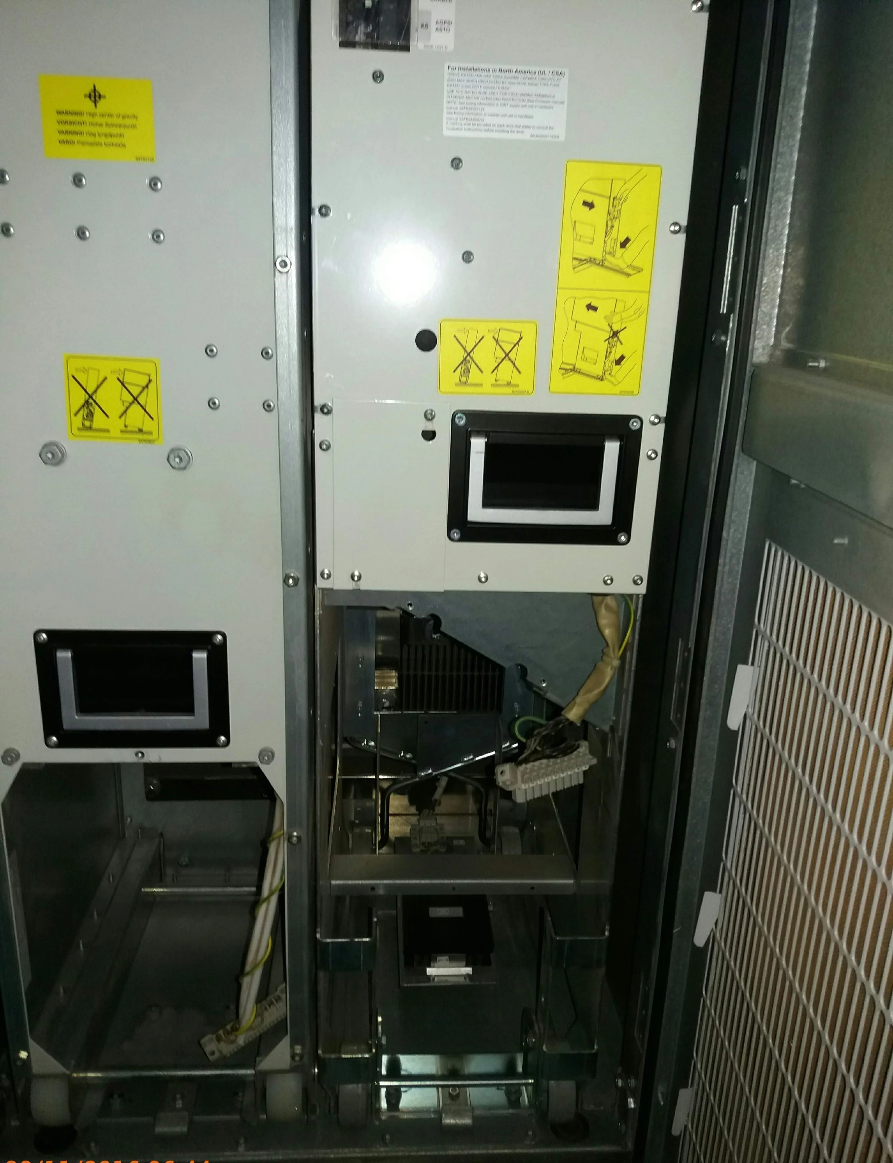
In the configuration documented here, a detected fault in the LCL cooling-fan circuit caused the inverter to trip its AC output. The fault information identifies the affected cooling circuit and helps direct the subsequent inspection.
The LCL Fan Fault — What the Inverter Display Showed
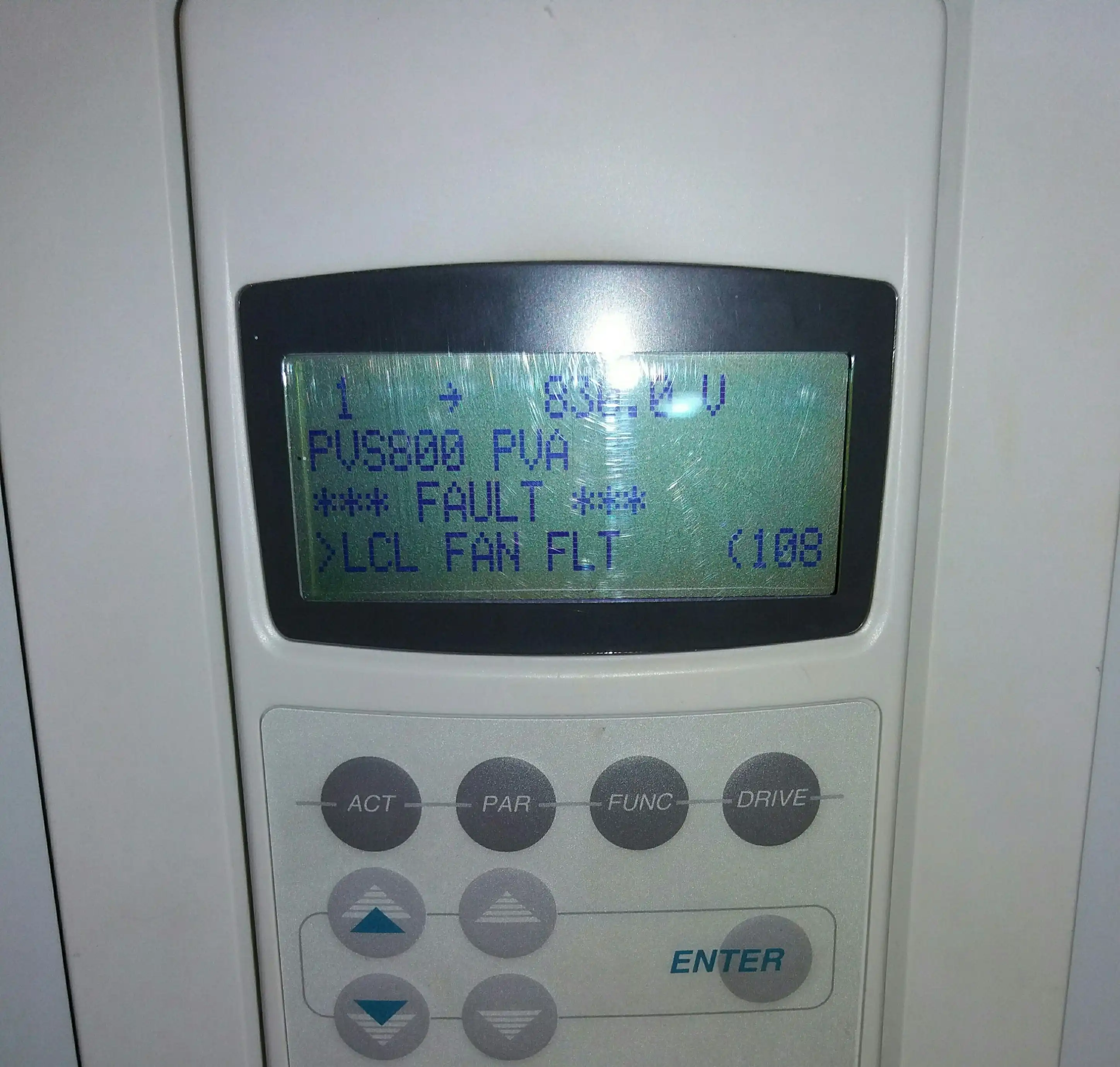
On the specific inverter documented here, the display showed: LCL FAN FLT (108). The DC bus reading of 830.0 V confirms the DC bus was energized at that moment. The photograph alone does not establish the complete event sequence — the inverter's event log and SCADA alarm history provide the full context on whether the cooling fault was the initiating event.
The fault indicates that the inverter's monitoring circuit detected an abnormal condition in the LCL cooling fan circuit. The fan motor itself may have failed — but the power supply wiring, terminal connections, and the monitoring or feedback circuit should all be checked before the root cause is identified. The same alarm can arise from a motor failure, a wiring problem, a mechanical obstruction, or a fault in the monitoring circuit itself.
Fault code assignments for cooling fan conditions vary between inverter manufacturers, firmware versions, and cabinet configurations. What the fault message establishes here is that the monitoring circuit has detected a condition it classifies as a cooling fault in the LCL section. The inverter's response — a controlled trip of AC output — is a protective action, not a component failure in itself.
Remote reset may clear the active fault condition and command a restart. It does not address the underlying condition. It does not establish that the underlying cooling problem has been corrected. Physical inspection of the fan unit, its power supply, wiring, its connection to the monitoring circuit is the required first step before reset. Resetting without finding the cause can result in a repeated trip or continued operation with inadequate cooling.
Power Module Temperature — Establishing a Baseline
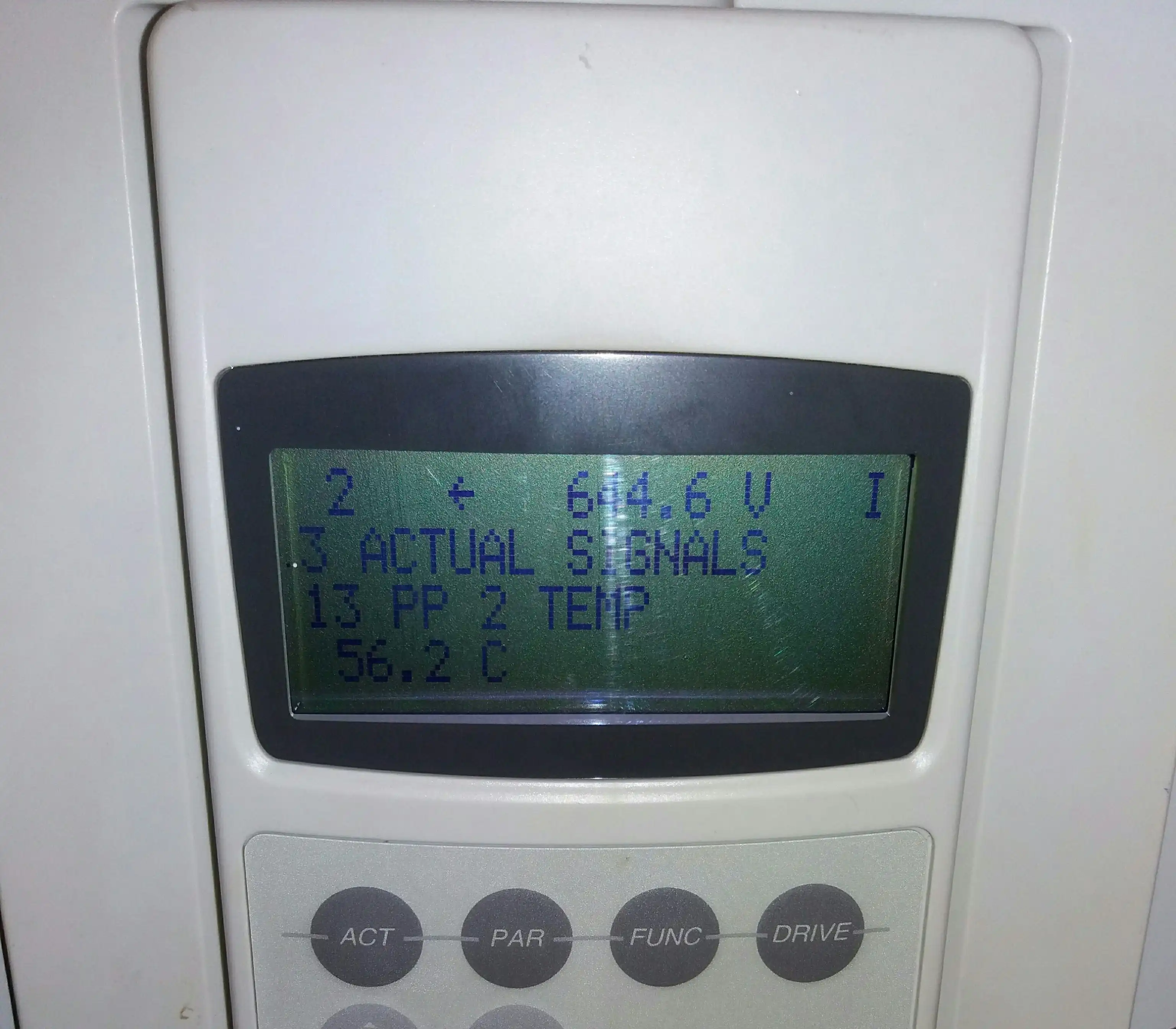
On the central inverter shown here, PP 2 TEMP identifies the measured IGBT temperature for power module No. 2, as documented in the inverter manufacturer's firmware reference. Other inverter platforms use different parameter names and may measure temperature at different physical locations in the thermal path.
The 56.2°C reading shown here is a normal-operation snapshot from this specific inverter, taken when the cooling system was functioning correctly. It should not be treated as a universal reference temperature for central inverters. The operating temperature for any given inverter's power module depends on the inverter model, firmware configuration, operating load, and measurement point. Temperature limits and protection thresholds are manufacturer-specific.
What the reading establishes is a baseline for this inverter under these conditions. A sustained upward shift on this parameter — same inverter, checked at comparable load levels and comparable ambient conditions over months — can provide an early indication that the inverter's thermal conditions are changing. It does not, on its own, identify the cause. The shift could reflect a degrading fan, a progressively blocked filter, dust accumulation on the heat-sink, or early-stage power module degradation. Temperature trend narrows the search to a specific unit. It does not close the diagnosis.
One boundary that applies to any external temperature monitoring point: under load, the semiconductor junction temperature will generally be higher than the temperature measured at an external point in the thermal path, with the difference depending on the module's internal thermal resistance and current power dissipation. A rise in the monitored temperature under comparable loading conditions therefore indicates a change in the thermal state of the power module, but it does not provide a direct value for junction temperature. For the physics of the IGBT thermal stack and how this applies to degradation diagnostics, refer to the companion article on IGBT failure in utility-scale solar inverters.
How the Cooling Fan Fails
A centrifugal blower fan in a central inverter operates for long periods under the site's actual conditions, including high temperatures, dust, and repeated heating and cooling. Over time, these conditions can contribute to several types of fan failure:
Bearing Wear
The motor shaft bearings are a common wear point in centrifugal blower fans. Their service life depends on the fan design, operating temperature, duty cycle, contamination, and manufacturer's specified conditions. Bearing degradation can produce a rising pitch, intermittent whine, vibration, or grinding noise before the rotor stops, but audible symptoms are not guaranteed. If the fan develops abnormal speed, current, feedback, or mechanical behaviour, the inverter's monitoring system may generate a fault depending on the available monitoring functions.
Dust Loading in the Impeller
Dust or dirt accumulated on the impeller blades can reduce airflow even while the fan motor continues to run, causing cooling performance to deteriorate before a dedicated fan fault is generated. In that situation, the first useful indication may be a change in power-module temperature under comparable operating conditions, with efficiency data providing additional evidence rather than proof of the cause.
Motor Winding and Electrical Connection Failure
Winding insulation degrades under sustained thermal stress and can fail without the audible advance signal that bearing wear provides. Separately, the fan motor connects to the inverter's auxiliary supply through a terminal block. Vibration and thermal cycling at the connector can increase contact resistance or open the connection entirely. Checking the terminal connection is the first diagnostic step — it is the quickest to correct if the motor itself is intact.
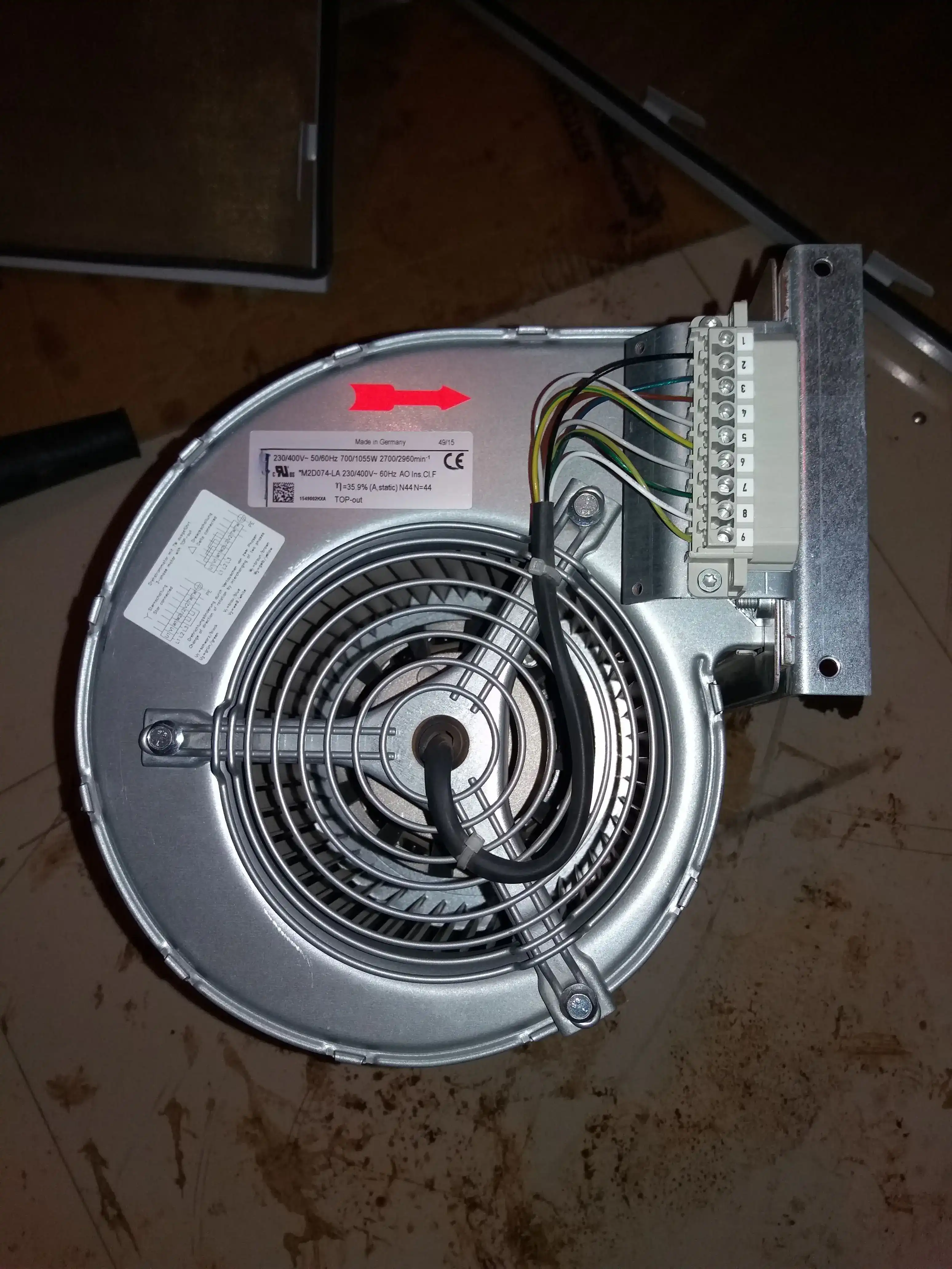
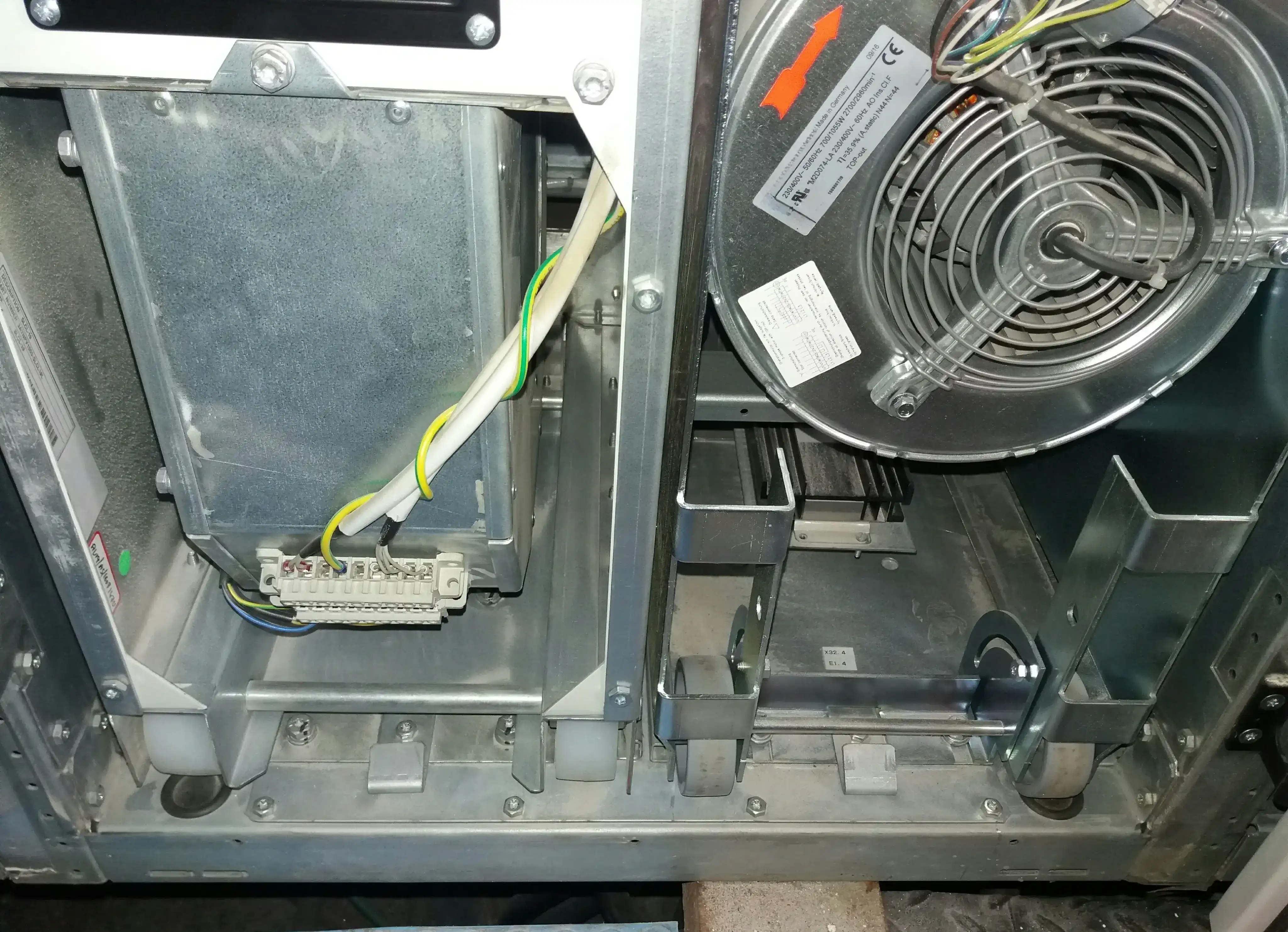
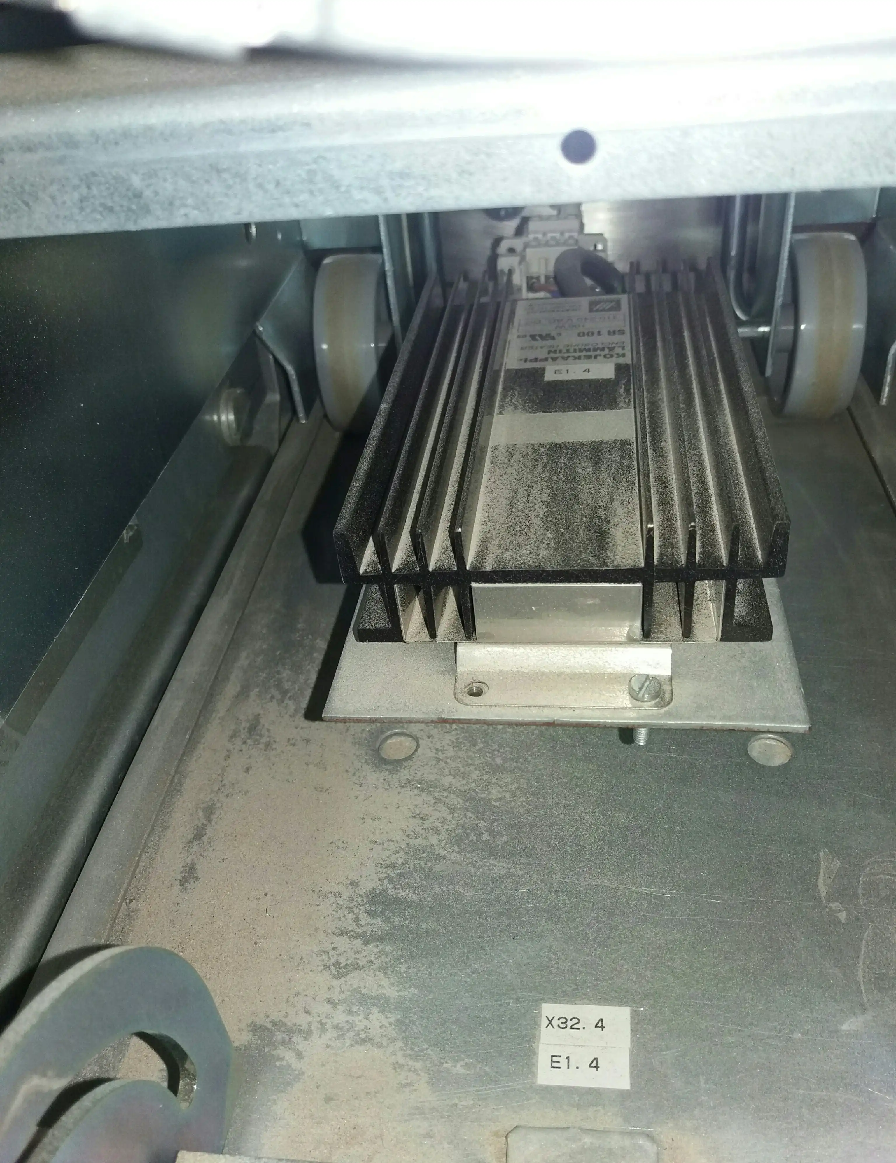
Dust on fins and a degraded fan compound each other: less air moving across surfaces that transfer heat less efficiently per unit of airflow. The combined effect raises steady-state power module temperature at a given output level and lowers the ambient temperature threshold at which the inverter reaches thermal derating conditions in summer.
When Cooling Failure Goes Undetected: A 1 MW Inverter Fire
I was called to a ground-mounted plant to assess a 1 MW central inverter after a fire. The plant team had already isolated both the DC and AC sides. When I opened the cabinet door, the inside was completely destroyed.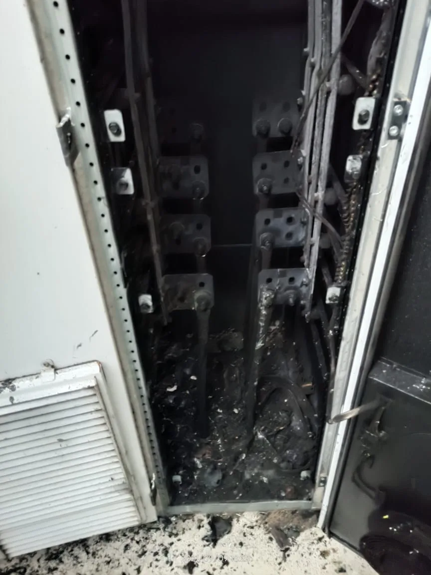
The air inlet condition ruled out an external fire. Everything was burned from the inside out. That directed the investigation straight to the inverter's internal thermal and electrical condition.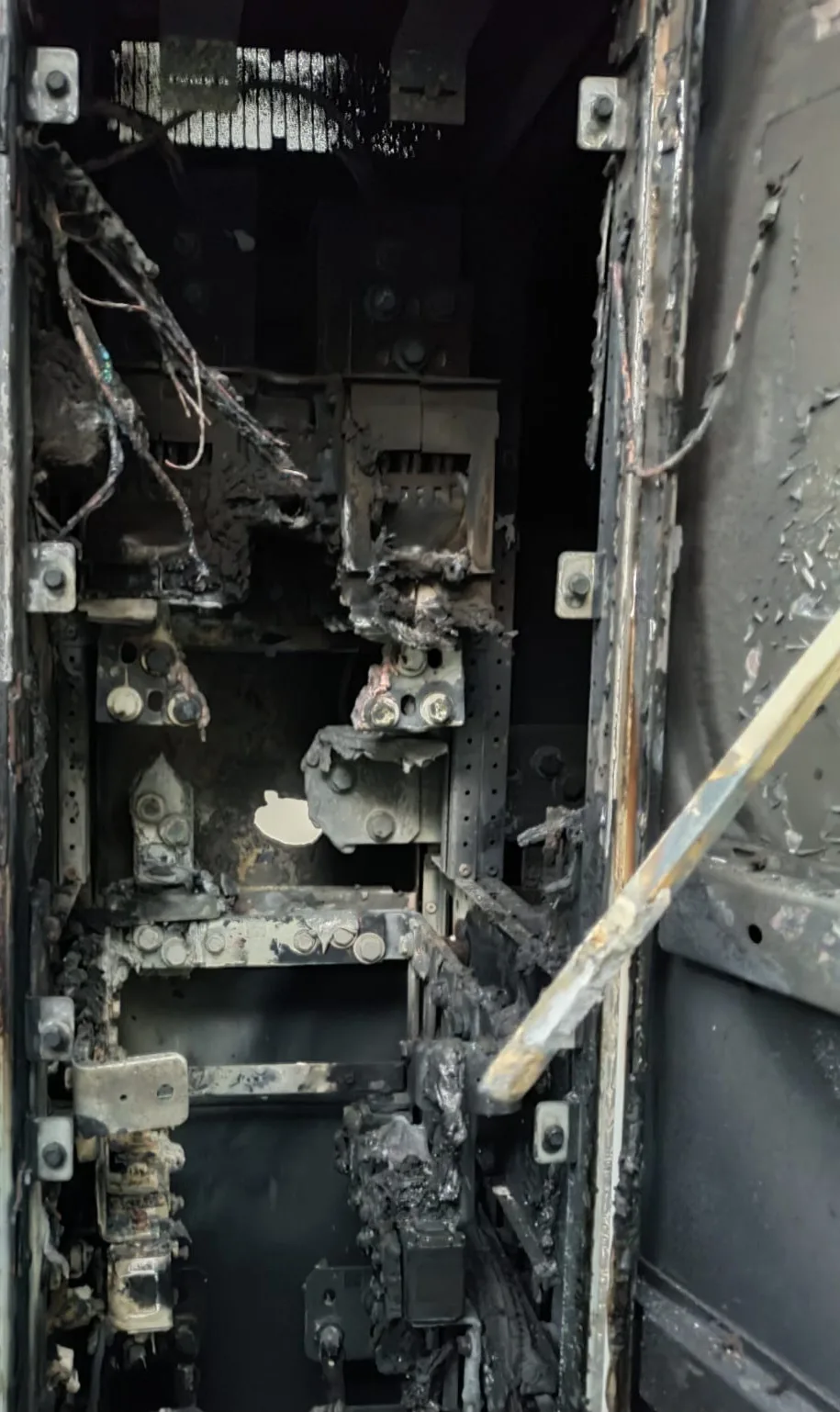
The fire was most severe in the IGBT section. The damage here was not random. The worst heat exposure was at the power module positions and the DC connections around them. That is where the fault started.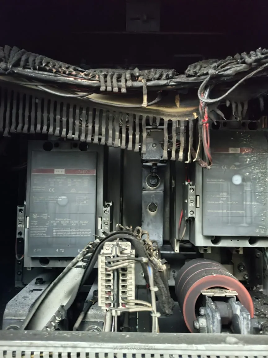
The AC cable damage tells you the fire propagated upward from the power stage. Once the DC fault arc formed below, it fed from the live PV array. DC current has no zero crossing to interrupt it. The arc then damaged the AC wiring above until the fault path itself burned open and cut off its own supply.
Physical Evidence and Failure Sequence
This did not happen suddenly. There was a sequence, and every step in it was detectable with basic O&M practice:
- The cooling fan had been failing for an extended period. Post-fire inspection found mechanical wear in the fan motor. Airflow had been reducing gradually, not all at once.
- Power module temperature was not being tracked. There was no baseline on record for this inverter, no periodic temperature log, no trend. The temperature was rising. Nothing flagged it.
- Months of high-temperature operation stressed the IGBT modules. This is the degradation mechanism covered in the companion article on IGBT failure in utility-scale solar inverters. Internal connections inside the modules progressively weaken under repeated thermal cycles above the rated range.
- Insulation failed at a DC connection inside the power stage. A short circuit formed. The PV array was live. By that point, the thermal protection the cooling system should have provided was already gone. Nothing slowed the fault.
- A DC arc established and propagated. It spread into the AC wiring above the power stage. The cables burned until the arc destroyed its own supply path.
The inverter was offline for months. A 1 MW inverter offline for that long is a generation loss worth calculating. The Plant & Grid Generation Loss calculator estimates lost kWh from the irradiance recorded during the downtime. For O&M contract reporting, the Plant & Grid Availability tool applies irradiance-weighted downtime so the calculation reflects when in the day the inverter was actually offline.
Step 1 in that sequence is the only point where this is inexpensive to fix. A worn fan, caught during a routine inspection, costs one replacement and one hour of work. Everything in Section 9 of this article exists because of what these three photographs show.
How Cooling Problems Can Appear in SCADA Data
Cooling-related problems can appear in different ways. A gradual cooling problem may cause temperatures to rise first, followed by power derating and then an inverter trip. A sudden fan failure or monitoring fault can cause an immediate trip without any clear warning in the performance data. High ambient temperature alone can also cause derating without a fan failure.These are possible patterns, not a fixed sequence that every cooling problem will follow.
What follows describes how each condition can appear in the data — not as a guaranteed sequence, but as possible manifestations depending on how the problem develops.
Rising Temperature With No Visible Output Change
When airflow is reduced but still sufficient to keep the inverter below its derating limit, power module temperature may rise relative to the established baseline while AC output continues to follow irradiance normally. A dedicated fan alarm may not appear at this stage. The useful signals are therefore a temperature trend under comparable load and ambient conditions and, where the SCADA data supports a valid comparison, a change in DC-to-AC efficiency at similar operating points. Neither signal alone establishes the cooling system as the root cause.
Thermal Derating: Output Is Restricted
When the power module temperature crosses the inverter's derating threshold, the inverter reduces AC output to bring temperature back within the control region. In SCADA data, this appears as a flat-top plateau in the AC power curve during peak irradiance hours. The irradiance continues rising. The inverter output does not follow. Other inverters in the same plant — with healthy cooling — continue to track irradiance normally.
Thermal derating can be harder to detect than a complete inverter trip because the inverter keeps running but produces less power. The reduced output can look like a normal part of the daily generation curve unless it is compared with inverter temperature data.
The Instantaneous PR tool is useful here: a drop in real-time PR on one inverter during stable irradiance, while others in the plant hold steady, is a derating signal worth investigating on-site.
Fault Trip: Complete Loss of AC Output
When the monitoring circuit detects that the fan has stopped — or that a temperature threshold has been crossed — the inverter trips its AC output. The power curve drops to zero. Irradiance continues accumulating in the PR and CUF denominators. This is the most visible and most clearly attributable loss in the monthly performance data.
How Cooling Failure Affects Inverter Efficiency, PR, and CUF
Inverter Efficiency
Elevated power module temperature increases the on-state resistance of the IGBT switching devices, increasing conduction losses at a given current level. The efficiency penalty is most significant at high output power — the peak-irradiance hours when thermal stress is also greatest.
However, a downward efficiency trend alone should not be treated as proof of thermal degradation. Efficiency changes with DC voltage, load level, ambient temperature, operating mode, and measurement accuracy. Compare the inverter against its own historical efficiency at similar DC power and operating conditions, and use temperature data and alarm history to investigate the cause. Use the Inverter Efficiency Dashboard to compare DC-to-AC efficiency across the plant's inverters at similar load levels. If one inverter's efficiency declines over time while other inverters at the same plant remain stable under comparable conditions, that is a useful signal for further investigation, not a confirmed diagnosis.
Performance Ratio
For the capacity-based PR method, AC energy is compared with the installed DC capacity and the available plane-of-array irradiation through the reference-yield formulation used for PV performance analysis. In simple terms, the numerator is the actual AC energy produced, while the reference yield represents the available solar resource relative to the standard reference irradiance. During thermal derating, actual AC energy falls while the available solar resource continues to accumulate, so PR decreases.
To reduce the effect of PV module temperature on seasonal PR variation, use Temperature Corrected PR. This helps separate temperature-related PV-side variation from other performance losses. If corrected PR declines during summer while the module-side temperature effect has been normalized, investigate inverter thermal behaviour alongside other possible plant losses. Temperature-corrected PR narrows the investigation; it does not identify an inverter cooling problem by itself.
Capacity Utilization Factor
CUF captures the cumulative generation impact across the reporting period. Each derating or trip reduces actual generation and therefore reduces CUF for the period. Because cooling-related derating can occur during high-irradiance periods, the generation loss from a given duration of derating can be greater than the loss from the same duration during low-irradiance operation. The actual CUF impact depends on the duration, severity, and timing of the event.
Use the Plant & Grid Generation Loss calculator to estimate the energy lost during a cooling-related trip. For availability analysis, the Plant & Grid Availability tool uses irradiance-weighted downtime so that periods with greater available solar resource carry more weight in the availability calculation. Apply the methodology required by the applicable O&M contract and monitoring standard for formal reporting.
Distinguishing Cooling Derating from Clipping and IGBT Degradation
This is where the diagnosis usually gets complicated. Three different conditions can produce a flat-top plateau in a central inverter's AC power trace during peak irradiance hours. A flat-top power curve alone is not enough to determine which one is present.
Inverter Clipping
A clipping plateau normally occurs at or close to the inverter's rated AC output, with the inverter operating within its normal thermal range. DC array output exceeds the rated AC capacity, and the inverter cannot convert more than its rated maximum. Clipping is predictable from the DC-to-AC capacity ratio and irradiance distribution — it is a design condition, not a fault. The article on inverter clipping in solar plants covers how to calculate the loss and its PR and CUF impact.
Thermal Derating from Cooling Failure
A thermal derating plateau can appear below the rated AC output and may coincide with elevated internal temperature or a thermal-limit signal in the inverter's monitoring data. Compare the plateau power level with the inverter's rated AC capacity and cross-reference the inverter's temperature and alarm signals at the same time. A plateau below rated capacity together with elevated temperature supports a thermal-derating diagnosis, but the complete operating condition should be checked before assigning the cause. Genuine clipping is an expected operating condition and does not require cooling-system maintenance.
IGBT Internal Degradation
IGBT degradation — bond wire fatigue, solder delamination — increases the module's internal thermal resistance. This produces additional heat at the same power throughput, which can also result in thermal derating with a similar SCADA signature. A sudden change in temperature behaviour can point toward a cooling-path problem, while a slow long-term temperature trend may also be consistent with internal power-module degradation. Temperature trend alone does not identify the root cause. It identifies the inverter that needs closer examination. The article on IGBT failure in utility-scale solar inverters covers those degradation mechanisms in detail.
In practice, a degraded cooling system accelerates IGBT thermal aging. Early corrective action on the cooling path — clearing a blocked filter, replacing a degraded fan — is the lower-cost intervention and also preserves power module service life. The two failure modes are not independent.
Practical O&M Checks
Intake Filter Condition at Every PM Visit
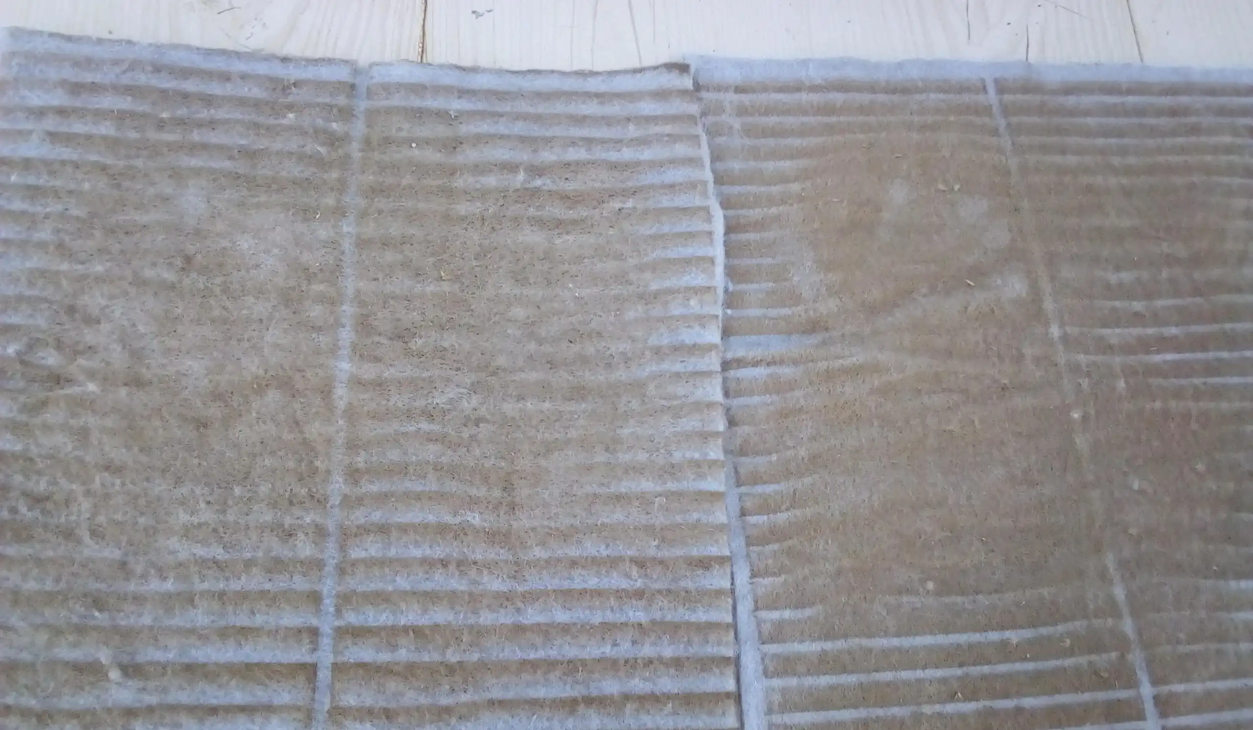
The intake filter mats keep dust and other particles from entering the inverter's cooling system. In dusty plant environments, the filter can become clogged and restrict airflow before the planned replacement date. A visual inspection can show heavy dust buildup, but it cannot tell you exactly how much the airflow has been reduced. Clean or replace the filter according to the inverter manufacturer's maintenance procedure and the site's conditions, then check that the cooling system is working properly.
Check for Unusual Fan Noise
Where the site's safety procedure allows it, listen for unusual fan noise from outside the closed cabinet while the inverter is running under load. A healthy centrifugal blower should produce a steady, consistent sound. Bearing problems can cause changes such as a higher-pitched sound, intermittent whining, or grinding. Detecting these changes early can allow the fan to be replaced before it fails and causes an unexpected inverter trip.
Safety note: Do not open energized inverter compartments for inspection unless the equipment's O&M procedure explicitly permits it and the required electrical-safety controls are in place.
Power Module Temperature — Periodic Logging
Navigate to the inverter's power module temperature signal — PP 2 TEMP in the inverter documented here, or the equivalent parameter in your inverter model's monitoring menu. Log the reading periodically under comparable conditions: similar time of day, similar irradiance level, similar ambient temperature. Note the AC output level at the time of each reading. Track the readings for each inverter over several months. If one inverter shows a sustained temperature increase while similar inverters remain stable under comparable conditions, inspect its cooling system.
Inverter Efficiency at Consistent Load Levels
Use the Inverter Efficiency Dashboard to compare DC-to-AC efficiency across the plant's inverters at comparable operating points over time. A downward trend on one inverter relative to its own historical baseline is a signal for further investigation. Cross-check the trend with temperature data, DC voltage, power level, operating mode, and alarm history before attributing the decline to a cooling problem.
Fan Fault Alarms — Physical Inspection Before Reset
Fan fault alarms require on-site physical inspection before reset. Check the fan unit, its power supply wiring, its terminal connections, and its interface with the monitoring circuit. A loose or open connection is the first thing to check and the simplest to correct. If the fan motor has failed mechanically, proceed with replacement per the inverter manufacturer's O&M manual before attempting a restart.
Note: Cooling system layout, fan monitoring arrangements, fault code assignments, temperature signal locations, and replacement procedures differ between inverter models and configurations. Always follow the specific inverter manufacturer's O&M documentation for any service action on a particular unit.
Key Takeaways
- Cooling architecture varies between inverter models. In the configuration documented here, the LCL section has a dedicated cooling-fan circuit, and the inverter reported an LCL fan fault when that circuit was abnormal.
- Cooling-related problems can manifest in different ways. A gradual deterioration may produce rising temperatures, then derating, then a trip. A sudden fan failure or monitoring fault can produce an immediate trip with no earlier warning in the performance data. High ambient temperature alone can cause derating without any fan failure. These are possible manifestations, not a guaranteed sequence.
- The power module temperature parameter — PP 2 TEMP in the inverter shown here, or the equivalent in other platforms — is a monitoring point for the inverter's thermal condition. Its diagnostic value is in a trend over months at comparable load and ambient conditions, compared against a documented baseline. A single reading is not diagnostic.
- Thermal derating and inverter clipping both produce a flat-top plateau in the AC power trace during peak irradiance hours. A flat-top curve alone is not enough to distinguish them. The plateau level relative to rated capacity, combined with inverter temperature data at the same time, is the diagnostic check.
- A fan fault alarm should be treated as a cooling-system issue requiring physical investigation. The alarm can arise from the fan motor, the power supply, the wiring, or the monitoring circuit. Remote reset without inspection does not address the condition.
- Cooling failure and IGBT degradation are not independent failure modes. A degraded cooling system accelerates IGBT thermal aging. Corrective action on the cooling system preserves power module service life and is the lower-cost intervention.
- Filter inspection, acoustic fan monitoring, and periodic temperature logging are the three O&M checks that can catch cooling degradation before it becomes a derating or trip event. All three can be executed within existing PM windows.
Frequently Asked Questions
What does an LCL FAN FLT fault mean on a central solar inverter?
It means the inverter has detected an abnormal condition in the LCL filter cooling fan circuit. The cause may be a failed fan, a problem with the fan's power supply or wiring, a mechanical obstruction, or a problem with the fan monitoring or feedback circuit. The fault does not by itself prove that the fan motor has failed. Check the fan, wiring, connections, and monitoring circuit according to the inverter manufacturer's troubleshooting procedure. The meaning of the fault code can vary by inverter model and firmware, so confirm the code in the manufacturer's documentation.
What is thermal derating in a central solar inverter?
Thermal derating is the inverter's self-protection response when an internal component temperature approaches or crosses a defined limit. The inverter reduces its AC output instead of continuing to operate at the same power level. In SCADA data, this can appear as reduced or limited AC output during periods of high irradiance. Possible causes include high ambient temperature, restricted cooling airflow, a degraded cooling fan, or other thermal problems inside the inverter A high-temperature condition does not by itself prove that the cooling fan has failed. If a cooling problem is confirmed and no other component has been damaged, correcting the cooling problem can restore the inverter's normal power capability.
How do I distinguish thermal derating from inverter clipping in SCADA data?
Both produce a flat-top plateau in the AC power trace during peak irradiance hours. A flat-top power curve alone is not enough to determine which condition applies. The diagnostic checks are: (1) compare the plateau power level against the inverter's rated nameplate AC capacity — a clipping plateau normally occurs at or near the rated output, while a derating plateau typically appears below it; and (2) check the inverter's temperature monitoring parameter at the same time — a clipping plateau occurs within the inverter's normal thermal range, while thermal derating coincides with elevated temperature or a thermal-limit signal. Multiple conditions can be active simultaneously, so interpreting the complete picture — plateau level, temperature, DC input, irradiance — is more reliable than any single check.
Can cooling fan failure lead to IGBT failure?
Yes, prolonged cooling problems can increase thermal stress on IGBT power modules and contribute to earlier failure. A cooling fan failure does not normally damage an IGBT immediately. If the inverter continues operating at higher temperatures, the repeated heating and cooling can increase stress on parts of the power module, including bond wires and soldered connections. Over time, this can contribute to degradation such as bond-wire damage or solder fatigue. The actual effect on module life depends on the inverter design, operating temperature, load pattern, and how long the module remains under increased thermal stress. Correcting a cooling problem promptly helps avoid unnecessary thermal stress on the power modules.
Which SCADA parameters help detect central inverter cooling degradation early?
Four parameters are most useful if available in your SCADA or inverter monitoring system: (1) Power module temperature — PP 2 TEMP or the equivalent for your inverter model — logged periodically at comparable load levels and ambient conditions, tracked as a trend per inverter over time; (2) fan fault alarm history — recurring fan fault codes, even ones that cleared with a remote reset, are pattern signals worth investigating; (3) AC output power during peak irradiance hours — any plateau below rated capacity on one inverter while others track irradiance normally; (4) DC-to-AC inverter efficiency at consistent load levels compared against the same inverter's historical baseline. No single parameter confirms the root cause. The diagnostic signal is in the combination and the directional trend over time.
References
- IEC 61724-1:2021. Photovoltaic system performance — Part 1: Monitoring. International Electrotechnical Commission. — Referenced for PV performance monitoring, performance-ratio methodology, and temperature-corrected performance analysis.
- Central solar inverter manufacturer's O&M and firmware documentation (the inverter configuration documented in this article). — Source for the cooling zone architecture, LCL section fan monitoring and fault detection, and the PP 2 TEMP parameter (documented as the measured IGBT temperature for power module No. 2 in the manufacturer's firmware reference).
- Centrifugal blower fan manufacturer's product datasheet (the fan model documented in the replacement event). — Nameplate specifications visible in the photograph: 230/400 V, 50/60 Hz, 700/1055 W input power, 2700/2960 rpm.
- Kull, K. et al. (2025). Comprehensive Diagnostic Assessment of Inverter Failures in a Utility-Scale Solar Power Plant: A Case Study Based on Field and Laboratory Validation. Sensors, 25(12), 3717. doi: 10.3390/s25123717 — Referenced for inverter failure diagnostics and root-cause validation methodology in utility-scale PV plants.
- Murdock, D. A. et al. (2006). Active Thermal Control of Power Electronics Modules. IEEE Transactions on Industry Applications, 42(2), 552–558. — Referenced for the thermal stack physics connecting external monitoring temperature to IGBT junction temperature, and the relationship between cooling path thermal resistance and power module stress.
Photographs are from utility-scale solar plant operations. Plant site identities and client details are not disclosed.